Principle
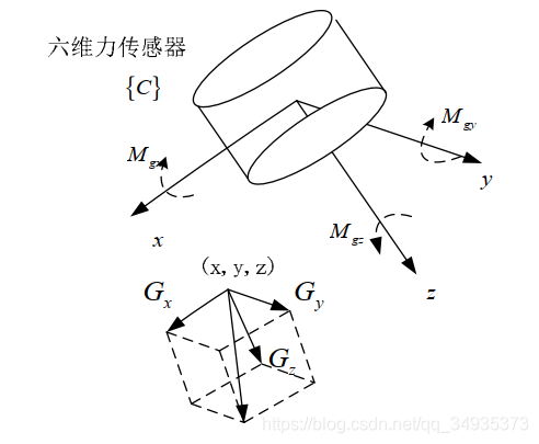
A six-axis force/torque sensor is a special force-sensing sensor that measures the forces (Fx, Fy, Fz) and torques (Mx, My, Mz) along the three axes of the Cartesian coordinate system, as shown in Figure 1.
The six-axis force/torque sensor is currently the most complete form of multi-dimensional force sensor. It provides robots with contact sensing, enabling them to perceive and adapt to changes in the external environment and thereby complete more complex and delicate tasks. It is a core component for compliant control and manipulation in robotics.
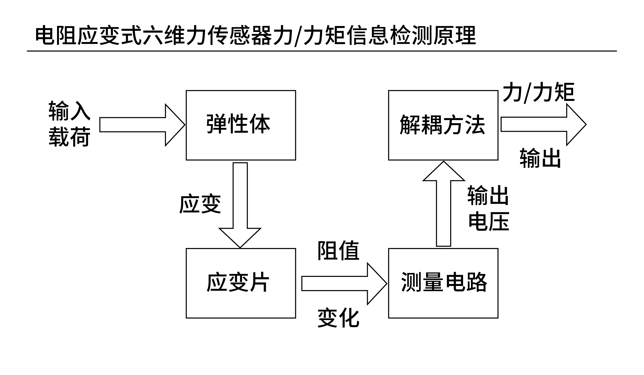
The six-axis force/torque sensor operates on the strain effect: when an elastic body is subjected to force/torque, the deformation of its shape changes the resistance of the strain gauges. Therefore, the sensor detects the tiny deformations caused by force/torque through strain gauges on the elastic body. The detection principle is shown below:
Advantages
-
The six-axis force/torque sensor offers high accuracy and strong anti-interference capability, and can be controlled along 6 axes (3 translational + 3 rotational). Each force corresponds to a vector with magnitude and direction; the calibrated sensor system is used to measure the magnitude and direction of forces in six directions, with calibration ensuring the accuracy and reliability of the measurement results.
-
The six-axis force/torque sensor has a wide load coverage range and can adapt to complex application scenarios. It can detect the three orthogonal forces and three orthogonal torques in any spatial force system, and is mainly used for force control and force-position control. In addition, high-precision military-grade six-axis force/torque sensors can keep measurement deviation within 0.3% FS under combined six-dimensional loading.
Application Scope
● Human-robot collaboration In human-robot interaction, the six-axis force/torque sensor can sense the contact forces and torques between the operator and the robot, providing a more natural and fluid interaction experience and offering diverse options for on-site operation.
● Collision detection During robot operation, the six-axis force/torque sensor precisely detects the forces on the robot's tool, enabling interactive perception of the surrounding environment and thereby determining whether a collision has occurred.
● Machining and polishing By sensing the forces on the robot's tool during the machining process, the system determines the angle and cutting force to use for the subsequent polishing operation. The six-axis force/torque sensor plays a very important role in machining and polishing processes.
The Six-Axis Force/Torque Sensor in the iNexBot Motion Control System
● In the iNexBot motion control system, the six-axis force/torque sensor is mainly used for drag teaching. It assists with dragging, making drag teaching less strenuous and operation smoother and more fluid. (Please note: perform dynamic identification before drag teaching!)
● Implementation: while dragging, the sensor reads the forces and torques at the robot tool tip in real time, and the system calculates the torque conversion value for each axis accordingly. During dragging, when the torque conversion value of a joint exceeds the configured joint friction compensation threshold, the system applies compensation to that joint (i.e., provides a certain push), improving the flexibility and adaptability of drag teaching.
Advantages of the Six-Axis Force/Torque Sensor in the iNexBot Motion Control System
-
High accuracy: according to customer field data, compared with drag teaching systems that use ordinary load identification, iNexBot's use of the six-axis force/torque sensor for assisted dragging improves accuracy by about 30%.
-
Flexible operation, simple and easy to understand. The iNexBot motion control system provides a dedicated software interface, communication and user operation parameters for the six-axis force/torque sensor. Customers do not need complicated operations — just click a button and let the iNexBot motion control system handle it in one step.
Detailed Steps
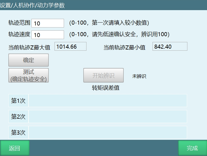
Identification
Identification is required before drag teaching. For the precautions and detailed operations, please refer to the Human-Robot Collaboration Operation Manual. The human-robot collaboration interface is shown below:
Installing the Sensor
After identification, install the sensor, with its positive X axis aligned with the robot's positive X axis.
Enabling the Sensor and Load
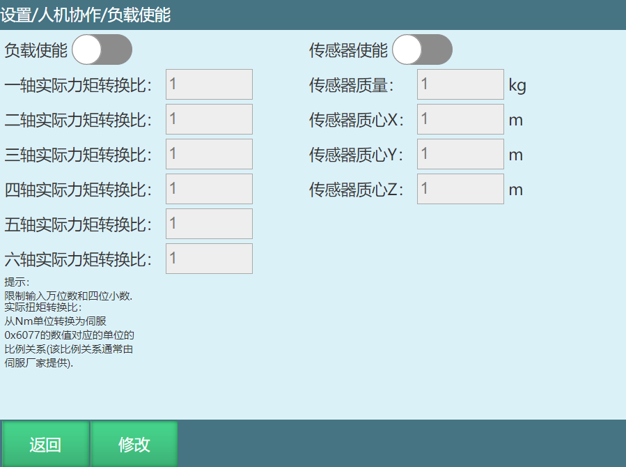
Before setting the six-axis force/torque sensor parameters, enable the sensor and the load. Go to Human-Robot Collaboration > Load Enable, click Modify, and turn on the load enable and sensor enable switches. The sensor mass and center of mass, the actual torque conversion ratio of each axis of the load, and the parameters of the sensor and the tool used (i.e., the load) are specified in the product manuals — configure them accordingly. The load enable interface is shown in the figure:
Six-Axis Force/Torque Sensor Parameter Settings
● Enter the six-axis force/torque sensor parameter settings interface In Human-Robot Collaboration > Drag Teaching, set the drag mode to "Torque", then click Parameter Settings. The "Six-Axis Force Sensor" button will appear on the Drag Teaching - Torque interface. Click this button to enter the six-axis force/torque sensor parameter settings interface.
● Sensor zeroing Before zeroing, make sure the sensor enable is on; otherwise, zeroing will report an error: six-axis force sensor not connected. Click the Zero button, and a dialog will prompt you to check whether there are obstacles around the robot; click OK to start zeroing. Do not approach the robot during zeroing to avoid accidents. The interface is shown below. Note: zeroing must be performed without a tool installed, to prevent the tool's load parameters from interfering with the calculation.
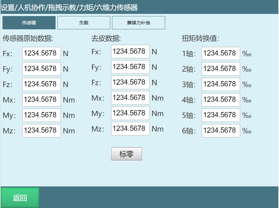
Sensor parameter descriptions:
● Sensor raw data: the raw data read by the sensor; Fx, Fy, Fz are the real-time forces, and Mx, My, Mz are the real-time torques.
● Tared data: the real-time forces and torques calculated from the raw data after removing the influence of the sensor's and the load's mass.
● Torque conversion value: effective in drag mode; the real-time torque conversion value of each axis calculated from the tared data. The larger the value of an axis, the greater the force on that axis.
Load Calculation and Result Import
● After zeroing is complete, install the load, click Calculate to compute the load's mass and center of mass, and write the results to the tool. Note: when installing the load, do not tighten the screws too much — it is enough that the load does not wobble after installation; otherwise, pressure on the sensor will skew the read data.
● Click "Write Result"; a dialog will appear where you can select the target tool. Click OK to write the calculation results into the selected tool's load parameters.
Checking the Written Load Parameter Values in the Interface
● In the Tool Calibration interface, select the tool to which the calculation results were written, and enter its load parameter interface to view the written mass and center-of-mass values. Note: you must select this tool and enable the load before entering drag mode. Otherwise, after power-on, the robot tip will sag due to unbalanced forces.
● If the correct tool is selected and the load is enabled, but the robot tip is still unbalanced after power-on in drag mode, the load parameters may have been calculated incorrectly. Adjust the load parameter values according to the direction of the robot tip's movement. For example, if the robot tip sags, the load mass is likely smaller than the actual value, so increase it appropriately. If the robot tip drifts toward the positive X axis, the center-of-mass X value is likely larger than the actual value, so decrease it appropriately.
Setting the Friction Compensation Threshold
The friction compensation threshold determines the range of torque conversion values that trigger system compensation. For example, if the friction compensation threshold for axis 3 is set to 50, then during dragging, when the torque conversion value of axis 3 exceeds 50 or falls below -50, the system compensates axis 3 (i.e., provides a certain push), making dragging on axis 3 smoother.
In summary, the six-axis force/torque sensor plays a pivotal role in the field of intelligent manufacturing, and with the support of the iNexBot motion control system, human-robot collaboration becomes even smoother. This not only improves the flexibility of drag teaching but also contributes to a higher degree of factory automation.