Overview
In robot application scenarios, handling and transfer tasks are very common. During transfer, gantry motion is used to prevent products and goods from being rubbed or collided with. With its ability to pick and place over obstacles at high speed, this motion pattern is widely used in the 3C industry and the palletizing industry.
In robotics, cycle time is the time required for a robot to complete the prescribed processing task for a workpiece; optimizing cycle time means improving robot production efficiency.
Gantry motion mainly consists of vertical lifting, crossing the obstacle, and vertical lowering. iNexBot strengthens the application of trajectory blending technology to optimize motion cycle time.
The Gantry Motion Command
A diagram of gantry motion is shown below:
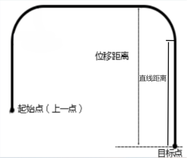
In the iNexBot motion control system, the gantry motion command is MOVARCH, described as follows:
MOVARCH Gantry Motion
1. Command Parameters
ARCH point, speed, smoothing level, acceleration/deceleration, displacement axis, displacement distance, straight-line distance, and advance execution time.
The gantry trajectory is determined by the following parameters:
a. ARCH point: the position of the key point in gantry motion, e.g., the target point;
b. Speed: the robot's motion speed during gantry motion;
c. Smoothing level: the smooth transition level between this command segment and the next;
d. Acceleration/deceleration: the acceleration ratio / deceleration ratio during motion;
e. Displacement axis: the robot can only rise along one of the X, Y, or Z axes (usually the Z axis);
f. Displacement distance: the distance to move along the displacement axis;
g. Straight-line distance: the vertical descent distance to the target point;
h. Advance execution time: how early the next command is executed.
In the iNexBot motion control system, create a new project file, then click Open > Insert > Motion Control > Gantry Motion to configure the gantry command, as shown below:

2. Interface Description
● V: motion speed, range 1-1000 (the default maximum Cartesian speed is 1000; the range varies with the actual Cartesian parameters entered), in mm/s.
● PL: smooth transition level, range 0-5.
● ACC: acceleration ratio, range 1-100, in percent.
● DEC: deceleration ratio, range 1-100, in percent.
● Displacement axis: (X, Y, Z) the axis along which displacement occurs during gantry motion; standard gantry motion displaces along the Z axis.
● Displacement distance: the distance to move along the displacement axis; standard gantry motion displaces 25 mm along the Z axis.
● Straight-line distance: the vertical descent distance from the straight segment along the displacement axis down to the target point.
● TIME: time, a non-negative integer in ms. Executes the next command this amount of time in advance.
Note: when the speed of a linear command is modified, the displayed acceleration and deceleration automatically maintain a 1:10 ratio with the speed; they can also be modified manually. The iNexBot gantry motion supports single-step and dry-run modes.
3. Usage Example
MOVARCH P0001 V=100mm/s PL=5 ACC=10 DEC=10 Z 25 0 This command means: during gantry motion from the current start point to target point P0001, the speed is 100 mm/s, the smoothing level is 5, the acceleration is 10%, the deceleration is 10%, the gantry height is a 25 mm displacement along the Z axis above the target point, and the straight-line distance is 0.
Barriers to Optimization
● Corner zone mechanism: when the robot needs to change direction between two consecutive paths, it usually needs a corner zone to transition due to inertia. Different robot brands may have different corner zone mechanisms, which affects the actual trajectory and cycle time.
● Electrical response time: the response time of the electrical system is also an important factor affecting cycle time. If the electrical system responds slowly, the robot will have delays in executing IO signals, affecting cycle time.
● Poor path planning: if the path planning for gantry motion is not well optimized — for example, too many sharp turns or unnecessary pauses — cycle time cannot be improved.
● Algorithm efficiency: the efficiency of the control algorithm is also a key factor affecting cycle time. If the algorithm has high computational complexity and slow processing speed, it cannot meet the demands of high-speed motion.
Improvements
To improve gantry motion cycle time, iNexBot uses its proprietary trajectory blending technology to improve the original standard gantry trajectory. The efficiency gains are as follows:
- By blending vertical ascent with horizontal motion, and horizontal motion with vertical descent, high-speed transitions between the vertical and horizontal trajectory segments are achieved without affecting obstacle crossing, improving efficiency.
- Since horizontal motion mainly serves to approach the target position and its pattern does not affect the task, a more efficient and smoother joint motion is used, while avoiding potential singularities and multiple-solution issues.
- A current-feedback control algorithm and an optimized trajectory interpolation algorithm are added, allowing the robot to run trajectories with higher acceleration while maintaining smooth operation.
- The trajectory smoothing algorithm is optimized, allowing the robot to run smoothly at higher speeds and accelerations during smoothing, reducing unnecessary pauses and sharp turns.
It is worth noting that in the iNexBot motion control system, the PL parameter of the gantry command does not represent the curvature of the arch segment in gantry motion, but rather — after trajectory blending — the smoothness of the transition between the current motion command and the next. According to tests by the iNexBot development department, the current trajectory blending method improves corner transition efficiency by 50% compared with conventional smoothing methods, fully demonstrating the advantages of iNexBot's trajectory blending technology. A brief diagram of trajectory blending is shown below:

Optimization Results
To verify the optimization effect, the iNexBot testing department conducted specific tests on the enhanced gantry command. The laboratory tests were as follows: ● Test environment: a four-axis SCARA robot with the following parameters:
| Parameter | Value |
|---|---|
| Joint speed | 5000 |
| Command speed | 5000 |
| Smoothing | 5 |
| Global speed | 100% |
| Acceleration multiplier | 15 |
| Deceleration multiplier | 15 |
| Minimum acceleration time | 0.02 |
● Test results: with a joint speed of 5000 rpm, long-term operation was fault-free, the cycle time remained stable at around 0.3 s, and the peak cycle time was optimized to 0.21 s, greatly improving the robot's work efficiency. Compared with other robots on the market, iNexBot's cycle time is 30% shorter.
Future Outlook
As described above, the iNexBot gantry motion command has demonstrated stable performance and already meets the diverse needs of customers. Looking ahead, more extended commands will be added to iNexBot motion control, aiming to further improve customers' palletizing experience. For example, the planned parameter set of the MOVARCH command will become: Arch point, speed, smoothing, acceleration/deceleration, rise direction, parameter table [0-7], maximum coordinate of the direction axis, and advance execution time. This change improves the command's ease of use. The planned extended gantry command MOVARCHEXT is described in detail below: MOVARCHEXT Extended Gantry Motion Command parameters: ARCHEXT target point, transfer point, approach point, speed, smoothing, acceleration/deceleration, parameter table [0-7], advance execution time. Gantry parameter settings Parameter table [0-6] (7 entries in total) specifies the transfer distance and approach distance of the gantry motion (see the figure below); the default parameters are shown in the table. Parameter table entry 7 defaults to standard gantry motion without trajectory blending.
| Index | Transfer distance | Approach distance |
|---|---|---|
| 0 | 30 | 30 |
| 1 | 40 | 40 |
| 2 | 50 | 50 |
| 3 | 60 | 60 |
| 4 | 70 | 70 |
| 5 | 80 | 80 |
| 6 | 90 | 90 |
The gantry trajectory is defined by teaching points (best understood together with the figures below): a. Current position: the robot's position when motion starts. b. Transfer coordinate: the position after moving from the current position along the positive Z direction of the tool coordinate system. c. Approach start coordinate: the position reached after crossing over from the transfer coordinate. d. Target coordinate: the end position of the gantry command. e. Transfer distance: the vertical rise distance from the current position (start point). f. Approach distance: the vertical descent distance to the target point.
In the figures below, Figure 4 is a conceptual diagram of the scenario, and Figure 5 is a motion trajectory diagram:


The addition of the MOVARCHEXT extended command will bring an improved user experience and better robot motion efficiency. We firmly believe that continuous technological innovation is the way to drive the sustainable development of intelligent manufacturing. Guided by the Industry 4.0 framework, iNexBot is resolutely leading the revolution of domestic robot technology. On this path forward, iNexBot never stops.