Communication between iNexBot and IOA Simulation Platform
iNexBot adopts TCP/IP communication method for communication with the IOA simulation. For the simulation module, a separate port 7000 is allocated for robot control and data communication using the socket communication protocol. Additionally, robot control and data communication can also be achieved through the iNexBot handheld device, enabling online simulation and control.

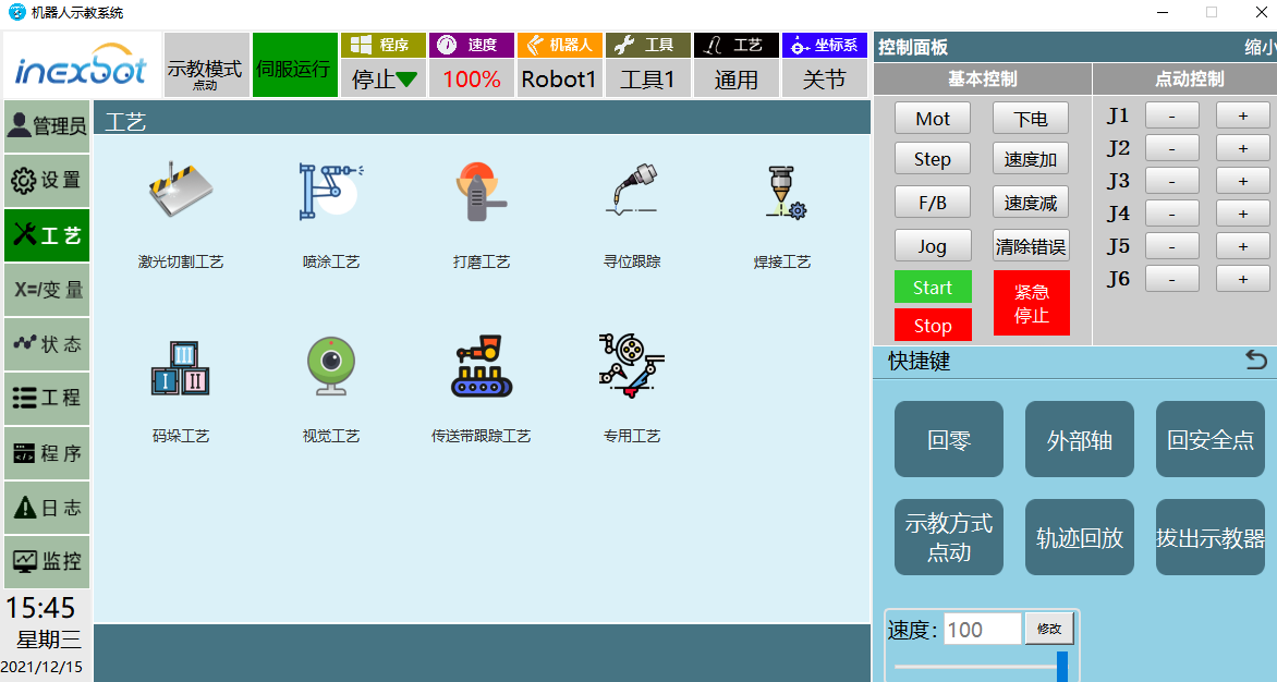
Creation Process of Palletizing Process
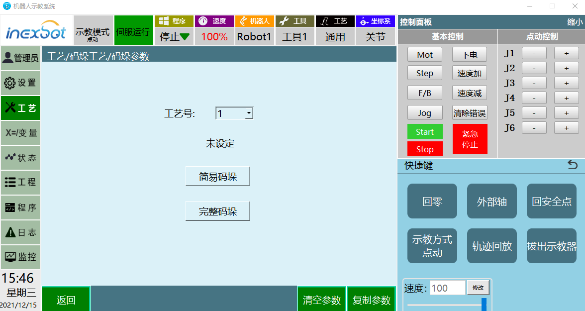
Each module in the system corresponds to a different process. In response to different market demands, separate modules for simple palletizing and complete palletizing are planned to meet simpler and more convenient requirements. Taking complete palletizing as an example, let's build a palletizing simulation system.
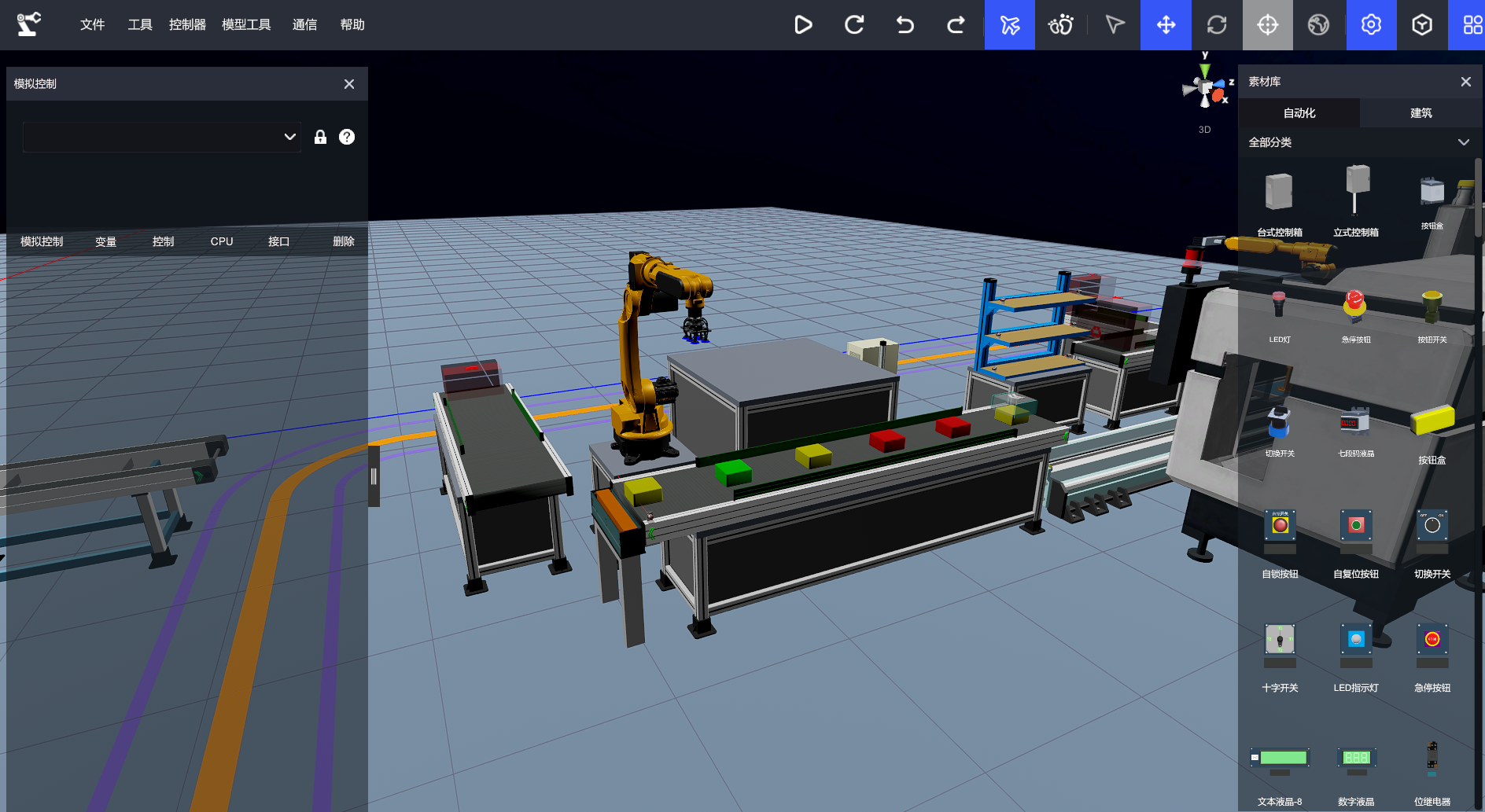
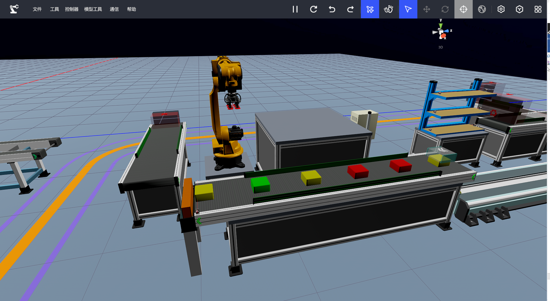
Based on the real production environment, a virtual factory is set up with elements such as conveyor lines, material generation, robots, sensors, and stoppers. This layout forms the basic environment for the robot palletizing workstation.
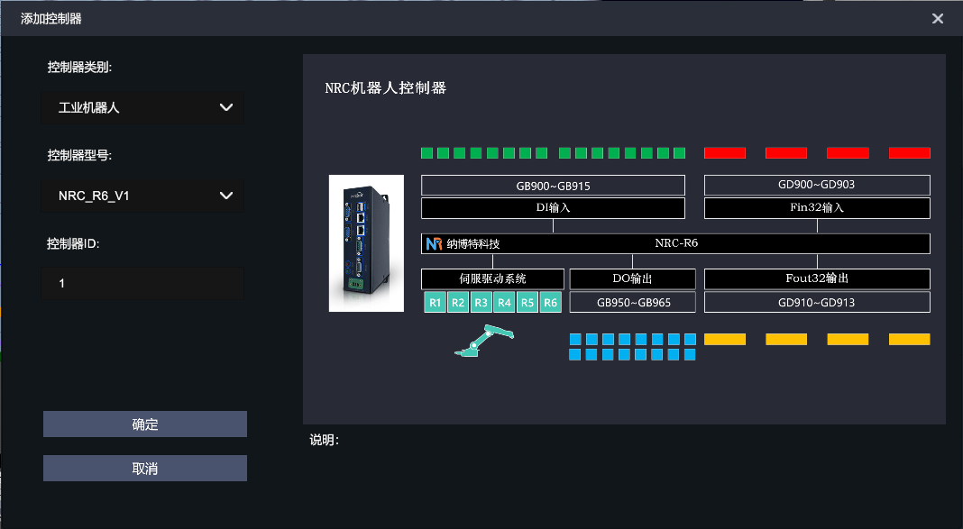
Model details and address allocation table are as follows:
| No. | Scene Model | Controller Address Allocation | Notes |
|---|---|---|---|
| 1 | ER20-1600_1--R6 servo | NRC_R6_V1 R6 | Robot control |
| 2 | Matrix suction cup-claw enable | NRC_R6_V1 GB950 | Suction cup enable |
| 3 | Geometric module generation-creation generation | NRC_R6_V1 GB951 | Material generation |
| 4 | PV conveyor belt_1--enable switch | NRC_R6_V1 GB952 | Material transportation |
| 5 | PV conveyor belt_2--enable switch | NRC_R6_V1 GB954 | Material transportation |
| 6 | Self-locking button--closed | NRC_R6_V1 GB950 | System startup |
| 7 | Diffuse reflection switch--obstruction | NRC_R6_V1 GB951 | Material detection |
| 8 | Blocking cylinder--enable | NRC_R6_V1 GB954 | Blocking material drop-off |
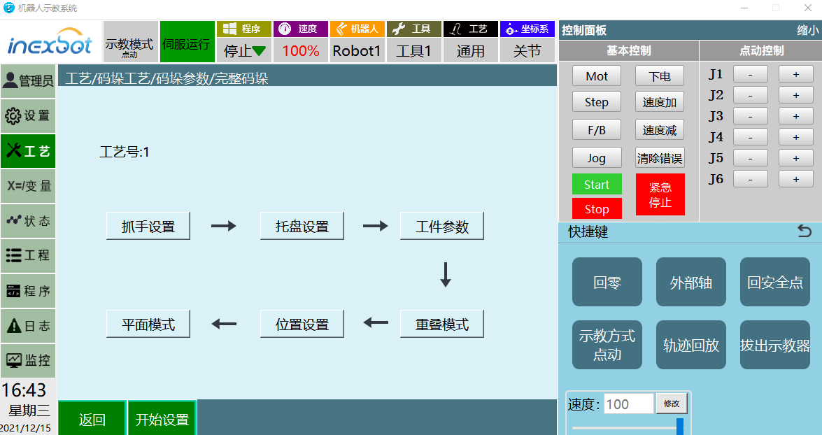
The basic environment setup is complete. Next, we move on to the palletizing process configuration:
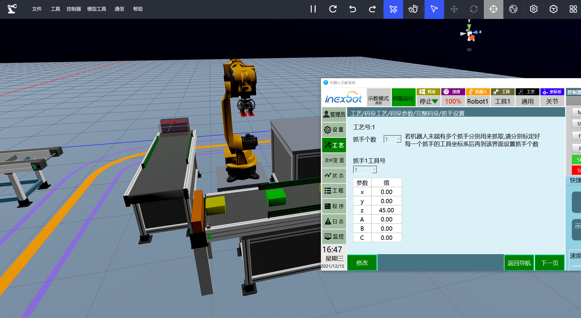
According to the navigation, the first step is to set the tool hand. Depending on different requirements, the number of tool grippers can be independently specified to meet the needs of single-tool or multi-tool palletizing.
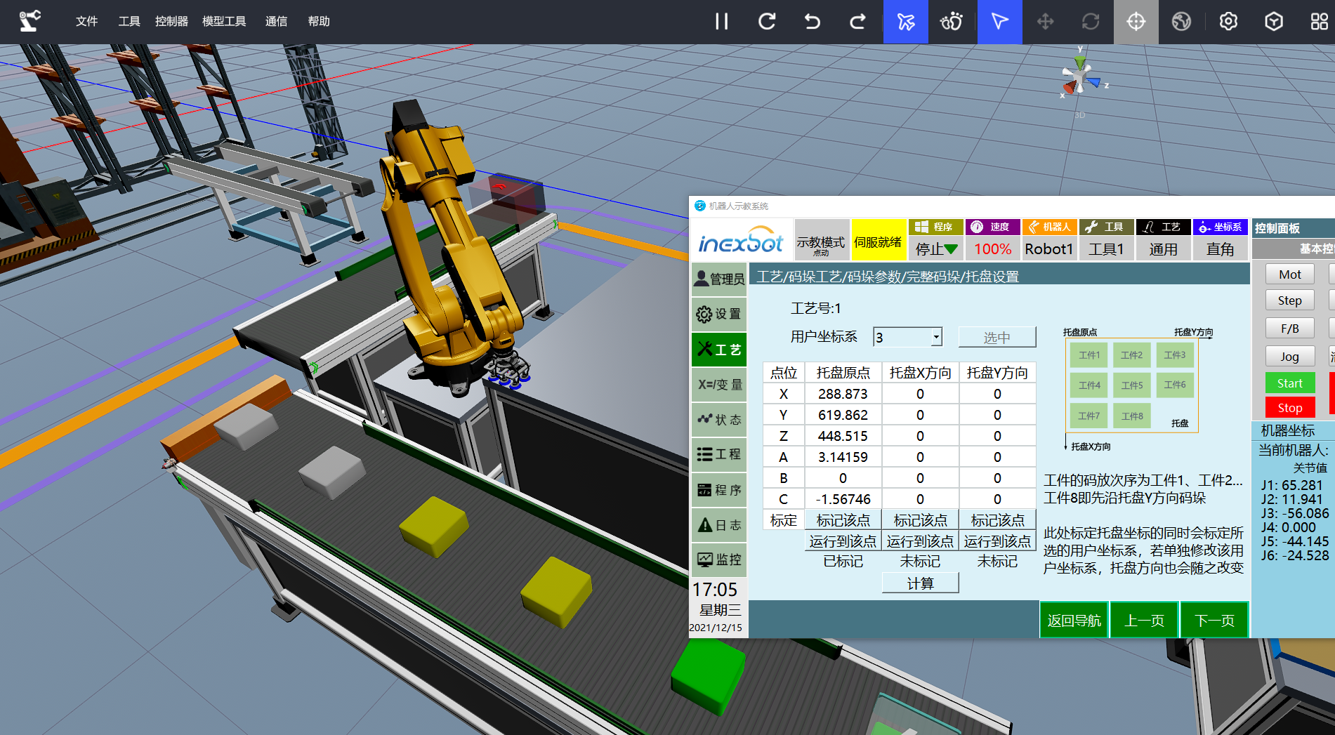
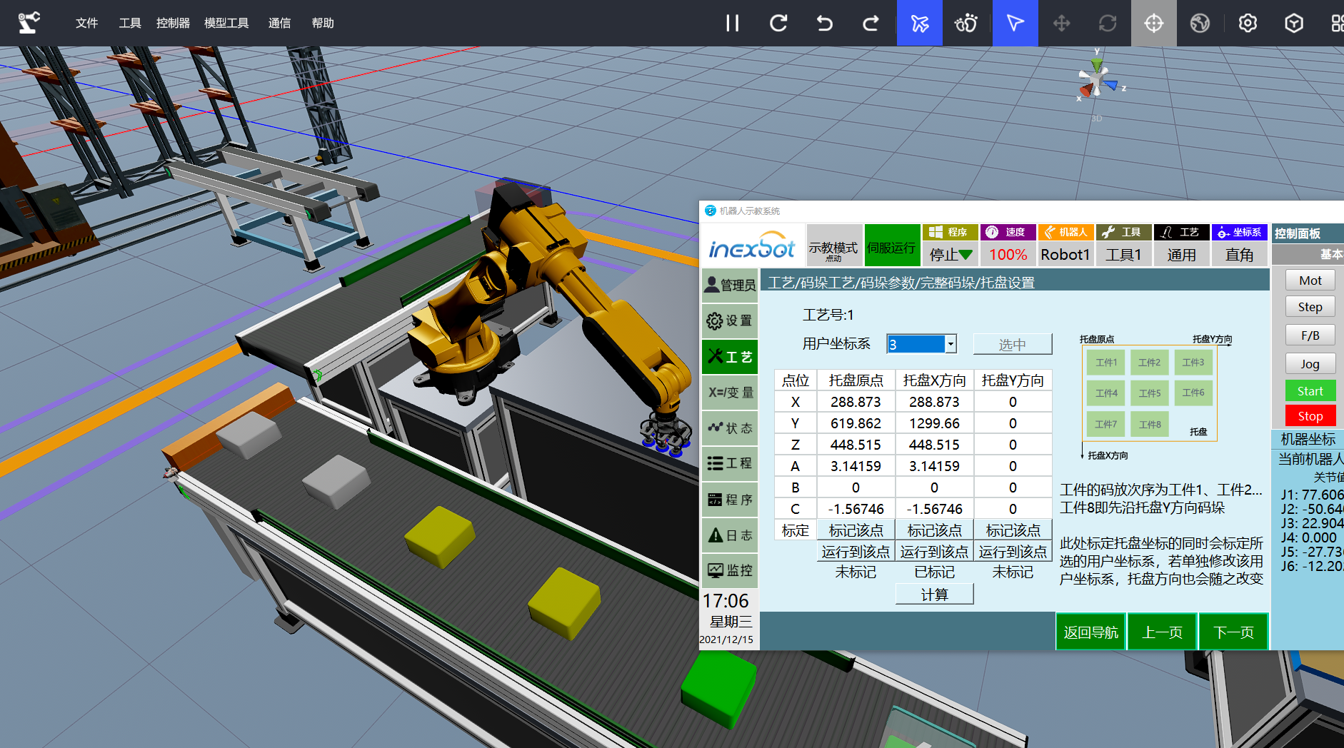
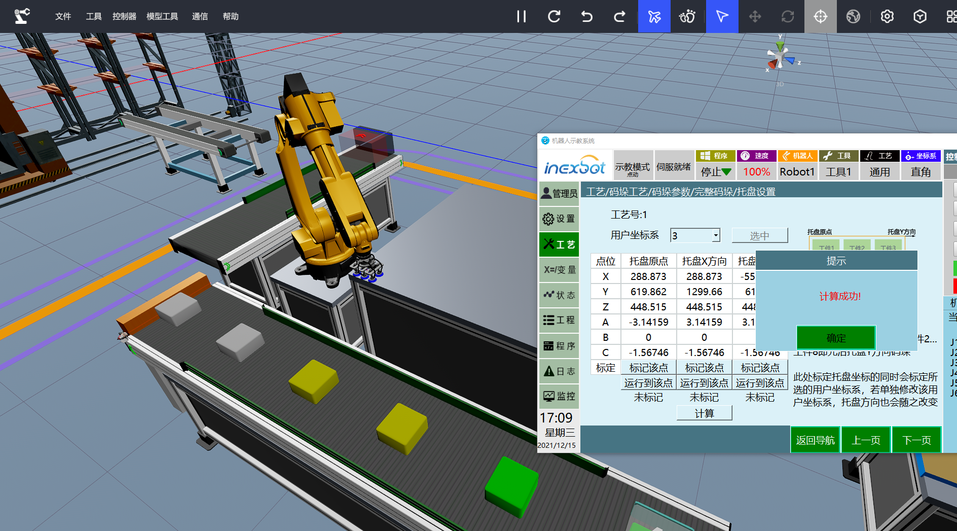
After setting the tool hand, the next step is to specify the position in the user coordinate system where the workpieces will be placed. This interface includes three modules: Mark this point, Move to this point, Calculate. Here, the X and Y directions represent only the directions.
Mark Tray Origin -> Mark Tray X Direction -> Move to Tray Origin -> Mark Tray Y Direction

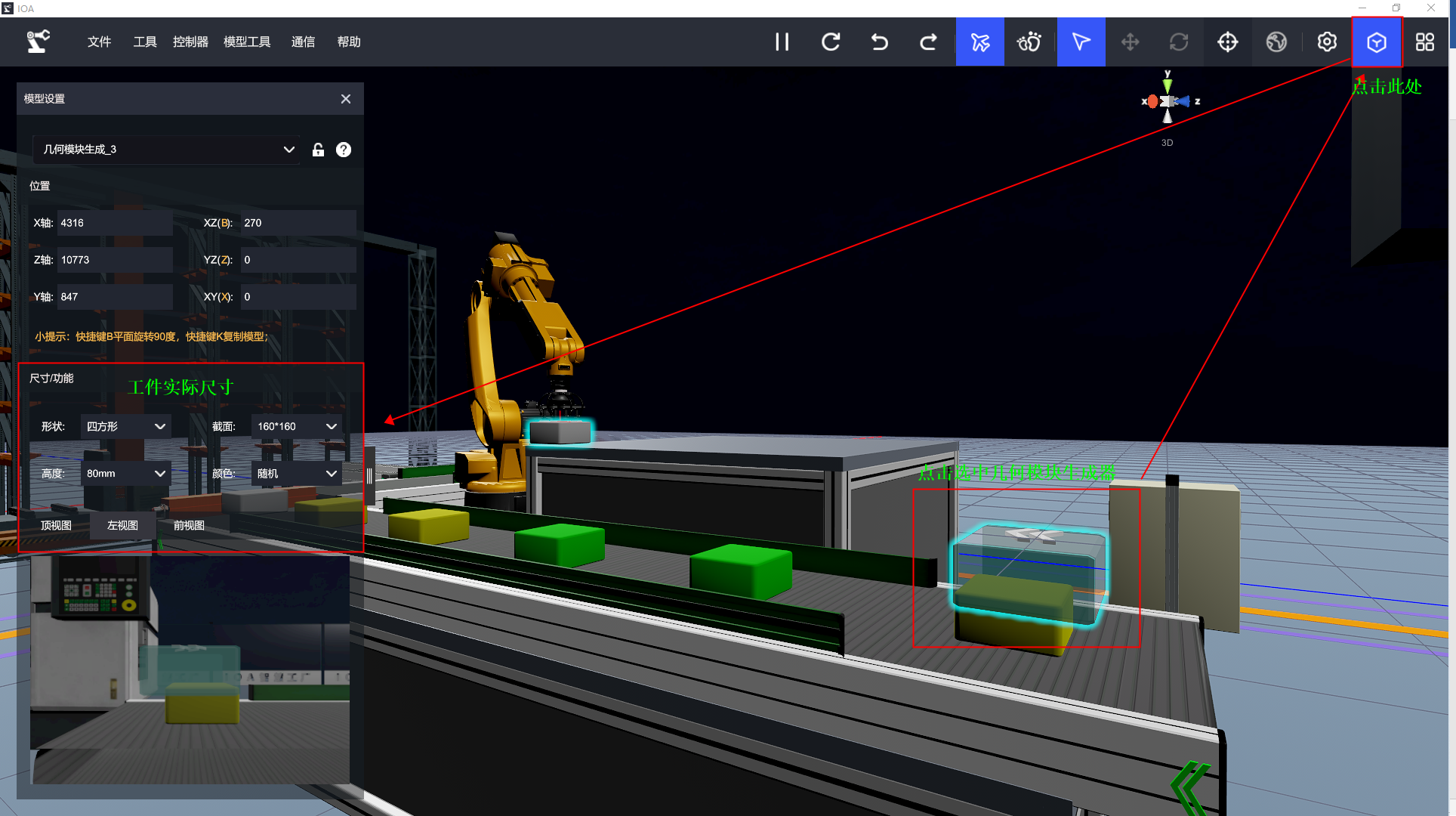
The next step is to set the dimensions of the workpiece. The dimensions should be set according to the actual workpieces. In the IOA simulation, the dimensions should be set to match the actual displayed size. In this case, the workpiece dimensions are set to 16016080, and there are no gaps between the workpieces in the X and Y directions (X=0, Y=0).

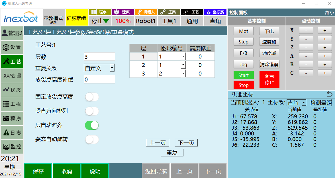
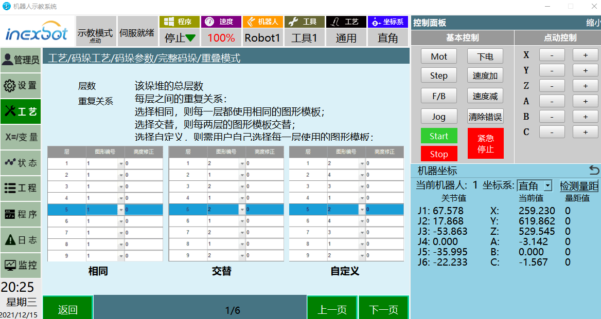
Click "Next" to enter the overlap mode. The overlap mode involves parameters such as the number of layers and the repetition relationship.
The number of layers is set to three, and the repetition relationship is selected as custom. The graphic number for the third layer is changed to 2.
Number of layers: Indicates how many layers the actual stack will have. In this case, we are stacking only three layers.
Repetition relationship: The repetition relationship can be the same, alternate, or custom.
Graphic number: The graph number is associated with the stacking pattern setting in subsequent stack design, and in this case, it is bound to the number of layers.
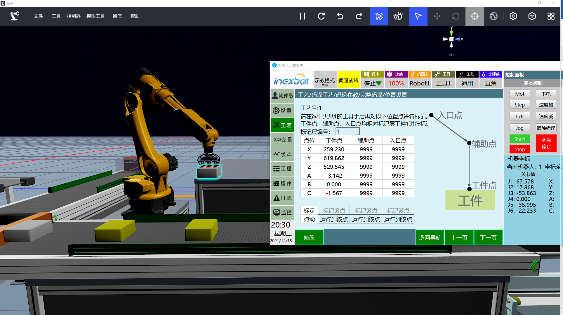
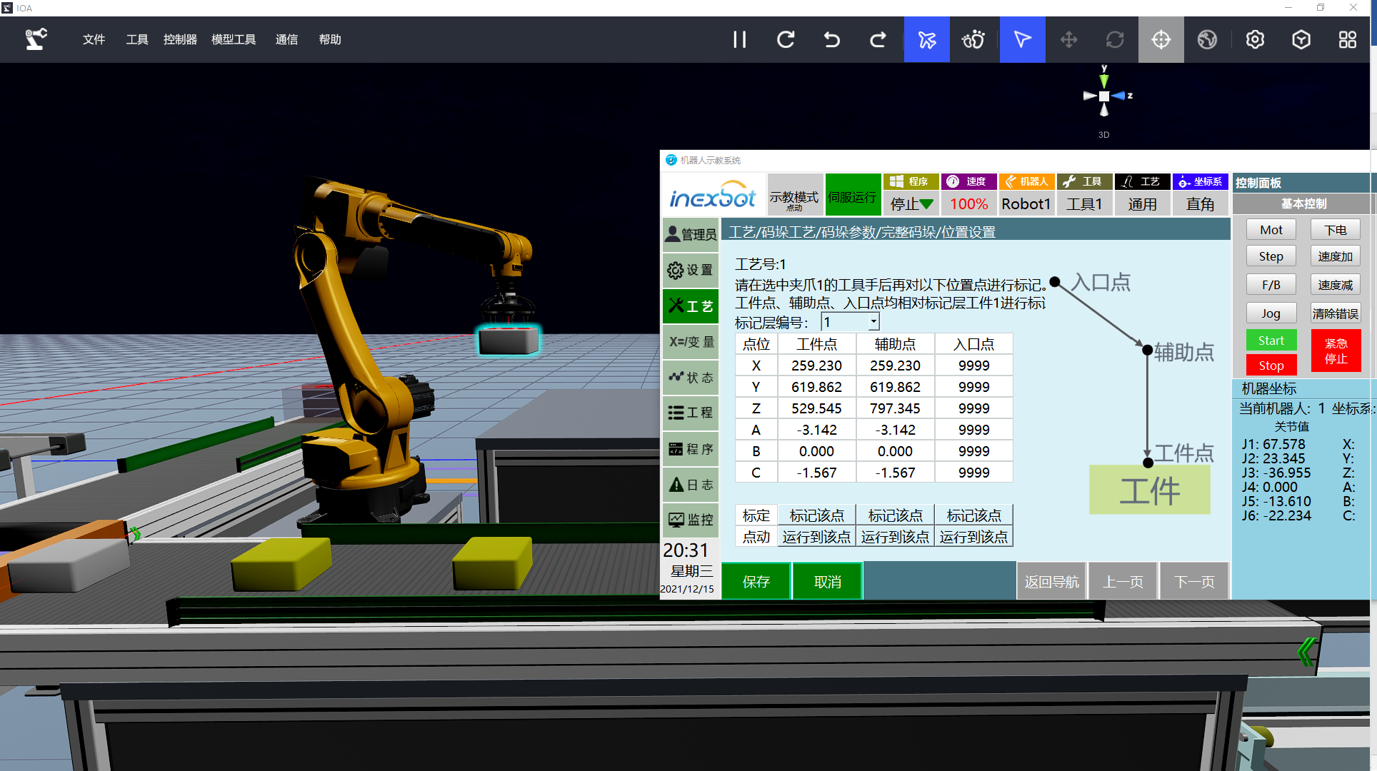
Once the dimensions of the workpiece are set, the next step is to set the actual position of our first workpiece in the user coordinate system. This includes the workpiece point, auxiliary point, and entry point. The calibration of these points is performed based on workpiece 1.

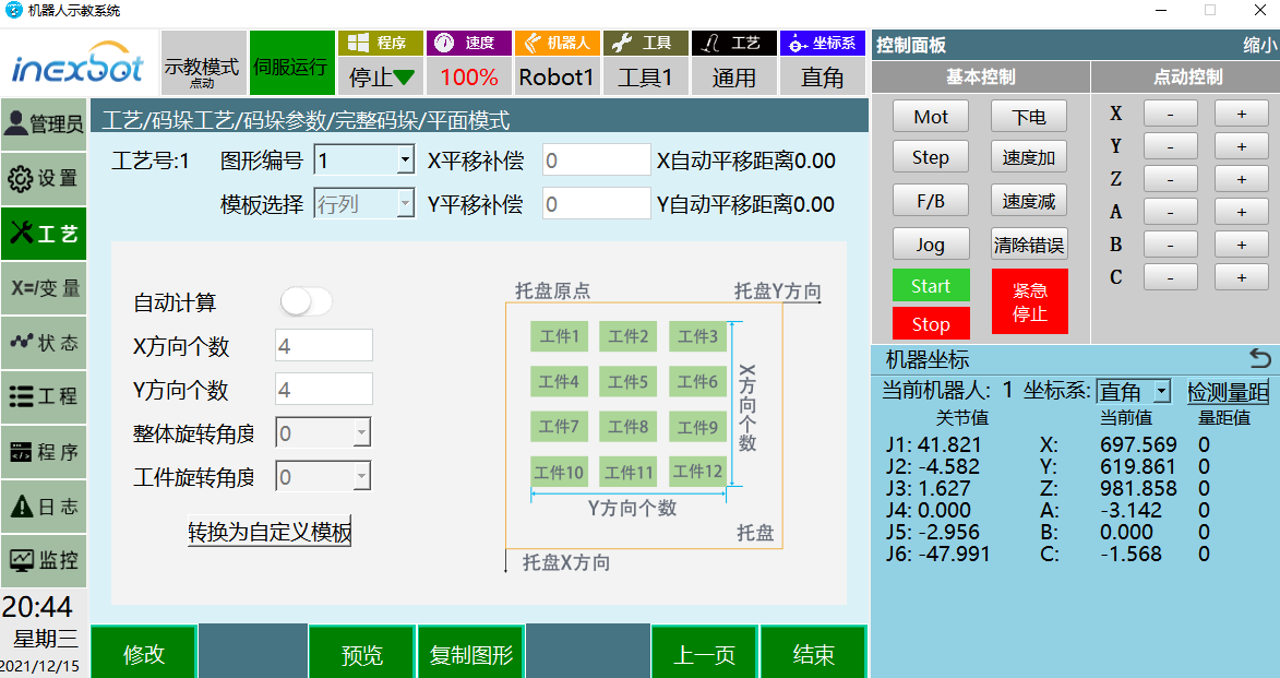
Click [Next] to enter the plane mode. The stacking patterns we offer for palletizing are diverse, including row-column mode, criss-cross mode, hollow square, five-flower stack, custom mode, and more, catering to various needs. Here, we will set the commonly used row-column mode. As mentioned before, there is a repetitive relationship between each layer. The first and second layers are associated with graphic ID 1, while the third layer is associated with graphic ID 2. Graphic ID 1 is set to have a row-column layout of 44, while graphic ID 2 is set to have a row-column layout of 22.

The IOA simulation platform configuration file and the iNexBot system job file and configuration file used in this article can be downloaded here
Here, our palletizing module setup is almost complete. The remaining task is to generate the program automatically. In the next chapter, we will begin introducing the palletizing instructions and automatic job file generation.