Why Industrial Robots Need Backlash Measurement
Industrial robots running long-term in heavy-duty applications such as welding, bending, loading/unloading, polishing, dispensing and stamping rarely lose accuracy suddenly. Deterioration is instead the cumulative result of reducer backlash, joint clearance and mechanical wear building up over time. The typical signature of this kind of transmission error: the robot looks normal on the surface, yet accuracy drops noticeably during trajectory reversals or load changes, and it cannot be corrected by re-teaching or modifying the program.
Traditional maintenance relies on "repair it only when it feels wrong":
- When accuracy degrades, it is hard to tell which joint is at fault or why, so the robot is often returned to the factory for a full overhaul, or components are replaced blindly;
- Sudden failures cause unscheduled downtime — on continuous lines such as welding and stamping, losses are counted in minutes;
- Inspection results are not archived or recorded, so no accuracy baseline can be established and deterioration trends cannot be tracked.
NexAutoCali joint backlash measurement replaces this workflow: a laser tracker provides quantified data for every joint, so every inspection leaves a traceable, verifiable record.
Solution Overview
A laser tracker performs single-joint motion measurement and trajectory performance diagnosis on the industrial robot, quantifying the backlash of each joint to provide data-driven evidence for maintenance decisions.
- Single-joint backlash measurement: each joint approaches the target position at low speed from the forward and reverse directions in turn, and the position difference between the two approaches is taken as the joint's backlash value;
- Single-joint repeat positioning accuracy: the joint repeatedly moves to the target position in the same direction to measure repeat positioning accuracy;
- Trajectory performance test: 14 performance indicators are tested in accordance with GB/T 12642—2013 to determine the extent to which backlash affects trajectories;
- Test report: a Word-format report summarizing the test environment, parameters, results and data charts.

Backlash Measurement Method
- Measurement procedure: each joint approaches the commanded position unidirectionally at low speed (1~5 °/s) → the arrival position is recorded → the joint approaches the same commanded position from the reverse direction → the difference between the forward and reverse arrival positions is the backlash; each joint runs 10 cycles in each direction, outliers are removed, and the mean is reported together with the standard deviation;
- Gravity effect elimination: the gravitational torque on the J2 and J3 joints varies with angle, introducing an elastic deformation component into the forward/reverse travel difference; this is eliminated through symmetric averaging and load compensation;
- Measurement uncertainty: the tracker's accuracy is ±10 µm + 5 µm/m; after amplification by the arm length, end-effector displacements of 0.02 mm are resolvable for J1 to J3. However, the near-end joints (J5, J6) have short arm lengths, so a backlash of the same magnitude produces very small end-effector displacement (1 arcmin of backlash at a 1 m arm length is about 0.29 mm, but only 0.03~0.06 mm at the short J5/J6 arm lengths). End-effector measurement alone therefore has low sensitivity for near-end joints; combining joint encoder data is recommended for a comprehensive assessment;
- Basis: the 14 performance indicators are tested per GB/T 12642—2013; the single-joint backlash measurement is a custom procedure (following the approach method of ISO 230-2, converted to the robot joints and set according to reducer manufacturer standards), and the basis is stated in the report.
Out-of-Tolerance Criteria
Reducer manufacturers usually give nominal values as angular backlash (arcmin), while the measurement side obtains end-effector displacement differences (mm). The two are compared after conversion via the joint arm length (the conversion factor depends on each joint's geometry; the software calculates it automatically and lists it in the report).
| Joint | Recommended Criterion (based on the reducer manufacturer's nominal value) |
|---|---|
| Base axes (J1~J3) | Out of tolerance if backlash exceeds 2× the reducer's factory nominal value — replacement or return to the factory is recommended |
| Wrist axes (J4~J6) | Out of tolerance if backlash exceeds 3× the nominal value (considering wrist-axis measurement sensitivity and repair cost) |
Criteria can be customized for the reducer models and working conditions used by the customer. After replacing a reducer, recalibration (zero position, geometric parameters) and retesting are required to restore accuracy.
Field Measurement Data
Example: an inspection of six 6-axis industrial robots on a welding line:
| Item | Data |
|---|---|
| Single-joint backlash measurement | 10 approach cycles per joint in each direction, about 5~10 minutes per joint |
| Full diagnosis (single-joint × 6 + 14 performance tests) | About 2 to 3 hours (incl. report); quick screening alone can be done within 1 hour |
| Findings | J3 backlash 0.12 mm, out of tolerance (2.4× the 0.05 mm nominal value, exceeding the 2× base-axis criterion) |
Technical Specifications
| Item | Specification |
|---|---|
| Measurement device | API Radian Plus / Pro / Core |
| Tracker accuracy | ±10 µm + 5 µm/m (per manufacturer datasheet) |
| Backlash measurement | Forward/reverse approach difference; mean of 10 cycles per joint in each direction |
| Diagnosis time | Quick screening (single-joint backlash) 5 to 10 min/joint; full diagnosis (incl. 14 performance tests) about 2~3 hours |
| Performance tests | 14 indicators per GB/T 12642—2013 (corresponding to ISO 9283:1998) |
| Report format | Word format, including test environment, parameters, results and data charts |
| Compatible models | 6-axis industrial (CBBABC), 7-axis collaborative (CBCBABC), 6-axis collaborative (CBBBAC), etc. |
| Data security | Offline mode supported; measurement data never leaves the site |
Key Advantages
Quantified Diagnosis: Know What Is Worn and How Far
- Backlash is measured joint by joint, identifying which joint is out of tolerance and by how much (e.g., "J3 backlash 0.12 mm, 2.4× the nominal value");
- Backlash data is compared against the historical baseline to judge whether wear has reached the replacement threshold;
- Accuracy problems are classified into "compensable by calibration" and "requiring mechanical repair", avoiding blind overhauls.
Fully Automatic Measurement: Diagnosis No Longer Depends on Specialists
- Measurement points are generated automatically and the measurement process runs automatically — no manual teach-point picking;
- Quick screening (single-joint backlash) takes 5~10 minutes per joint and can be scheduled within planned downtime windows;
- A single software suite handles everything: laser tracker measurement, robot motion control, calibration and testing, and algorithm computation are integrated into one package.
National-Standard Compliance: Traceable, Archivable Reports
- The 14 performance indicators are tested per GB/T 12642—2013;
- Test reports can export the test environment, parameters, results and data charts (Word format);
- An equipment accuracy archive is established to support warranty, acceptance and maintenance decisions.
Application Scenarios
| Scenario | Typical Problem | Expected Benefit |
|---|---|---|
| Welding robots | Weld trajectory deviation, drift of arc-start/arc-end positions | Pinpoint the backlash source and repair it in a targeted way, avoiding full-robot overhauls |
| Bending/stamping loading & unloading | Positioning errors on reversal, pickup offsets | Quantify backlash and assess whether the reducer needs replacement |
| Dispensing/spray painting | Uneven bead width, joint misalignment | Distinguish backlash issues from program issues, reducing rework |
| Heavy-duty handling | Accuracy loss after prolonged heavy loads | Establish an accuracy baseline and enable predictive maintenance |
Why Choose NexAutoCali
- Measurement hardware: API Radian Plus / Pro / Core or Zhongtu Instruments laser tracker, accuracy ±10 µm + 5 µm/m, measuring the robot's actual pose errors;
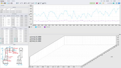
- iNexBot proprietary software: the robot calibration system and robot performance test system are combined into one; measurement points are planned automatically and the whole process runs automatically;
- National-standard validation system: 14 performance indicators tested per GB/T 12642—2013 (corresponding to ISO 9283:1998);
- Continuously expanding model support: already compatible with 6-axis industrial (CBBABC), 7-axis collaborative (CBCBABC) and 6-axis collaborative (CBBBAC) models. Model codes describe joint configurations by axis-sequence letters; see the product catalog for load ratings and the compatibility list.
Implementation Workflow
- Environment preparation: install the laser tracker and connect the robot, about 5 minutes; tracker warm-up and coordinate-system alignment are additional;
- Single-joint measurement: each joint approaches at low speed in both directions to measure backlash and repeat positioning accuracy;
- Overall testing: run the trajectory performance test and the 14 national-standard performance indicator tests;
- Data analysis: the software identifies joints with out-of-tolerance backlash and assesses severity against the criteria;
- Report output: a Word-format test report with test data and charts is generated;
- Maintenance decision: based on the data, schedule reducer replacement (per manufacturer procedure), check preload, or apply calibration compensation.
Deliverables
- Single-joint backlash and repeat positioning accuracy measurement data;
- 14-indicator performance test report (Word format);
- List of out-of-tolerance joints with maintenance recommendations (including replacement-threshold rationale);
- Accuracy archive (historical reports archived for later comparison);
FAQ
What is the difference between backlash measurement and robot calibration?
Calibration corrects parameters to restore accuracy; backlash measurement diagnoses the health of the transmission system, answering "why did accuracy drop and where is the fault". The two can be combined: first measure and localize the problem, then calibrate to compensate correctable errors; mechanical issues that calibration cannot eliminate go through the repair process.
Does measurement require downtime?
Yes. Quick screening (single-joint backlash) takes 5~10 minutes per joint, and a full diagnosis takes about 2 to 3 hours; scheduling within planned downtime windows is recommended. The fully automatic process minimizes downtime.
Can it determine whether a reducer should be replaced?
Yes. Single-joint backlash data is compared with the historical baseline and the reducer's nominal value; exceeding the criterion (e.g., 2× the nominal value) is sufficient to decide, avoiding the "you only know after disassembly" situation. After replacing a reducer, recalibration and retesting are required.
How often should measurement be performed?
Establish an accuracy baseline at new-machine acceptance, then retest every 3 to 6 months; heavy-load or continuous-operation conditions may warrant shorter cycles. Increase measurement frequency when abnormal trends appear. Calibration-type work (e.g., flexible-arm stiffness compensation) is recommended every 6~12 months — measure first, then calibrate: repair any mechanical issues found by measurement, then calibrate to compensate parameter issues.
What is the relationship between backlash measurement and flexible-arm stiffness compensation calibration?
They are complementary: backlash measurement answers "why did accuracy drop and where is the fault" (mechanical issues), while stiffness compensation calibration answers "how to correct compensable errors" (parameter issues). The same applies to collaborative robots: measure and localize mechanical backlash first, then calibrate to compensate deformation errors. See "Flexible-Arm Stiffness Compensation Calibration" in the Industry Solutions section.
Is the robot arm brand limited?
Measurement and reporting services already support 6-axis industrial (CBBABC), 7-axis collaborative (CBCBABC) and 6-axis collaborative (CBBBAC) models; other models are being added. Automatically correcting joint commands based on backlash data requires the iNexBot control system.
How is data security ensured?
Offline mode is supported, so measurement data never leaves the site; reports can be desensitized at the customer's request.